|
Nissan Rogue Service Manual: Fuel tank
Nissan Rogue Service Manual / Engine / Fuel System / Removal and installation / Fuel tank FWD FWD : Exploded View
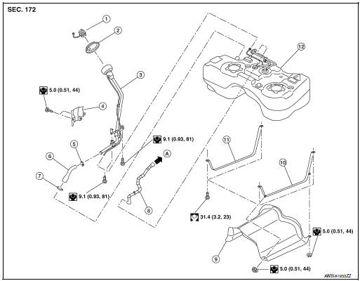
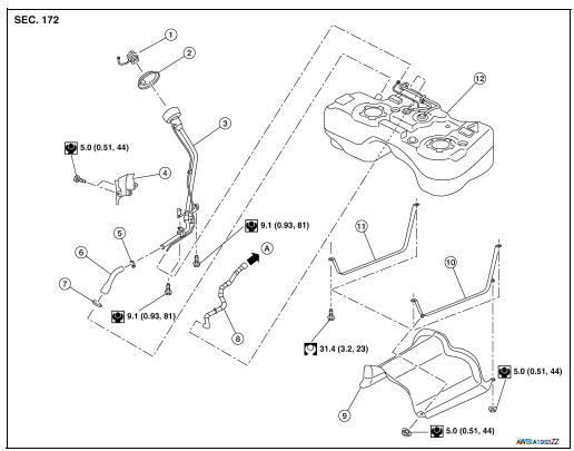
Fuel filler cap Grommet Fuel filler tube Cover Clamp Fuel filler hose Clamp Vent hose Fuel tank protector Fuel tank strap (LH) Fuel tank strap (RH) Fuel tank To EVAP canister
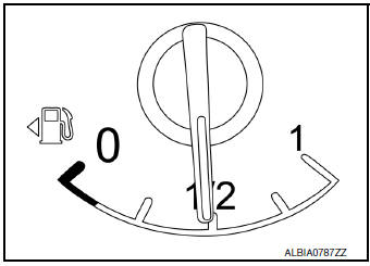
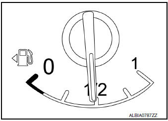
FWD : Removal and Installation REMOVAL WARNING: Be sure to read “General Precautions” when working on the fuel system. Refer to FL-2, "General Precaution". Check the fuel level with the vehicle on a level surface. If the fuel gauge indicates more than the level as shown (1/2 full), drain the fuel from the fuel tank until the fuel gauge indicates a level at or below as shown (1/2 full). In case the fuel pump does not operate, use the following procedure. Insert fuel tubing of less than 25mm (0.98in) diameter into the fuel filler tube through the fuel filler opening to drain fuel from the fuel filler tube. Disconnect the fuel filler hose from the fuel filler tube. Insert fuel tubing into the fuel tank through the fuel filler hose to drain fuel from the fuel tank. As a guide, the fuel level reaches or is less than the level on the fuel gauge as shown, when approximately 27.5
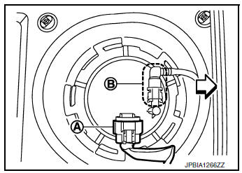
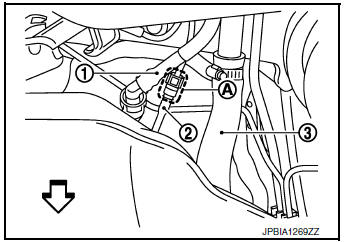
Release the fuel pressure from the fuel lines. Refer to EC-144, "Work Procedure". Disconnect negative battery terminal. Refer to PG-75, "Removal and Installation (Battery)". Unscrew the fuel filler cap to release the pressure inside the fuel tank. Remove second row seat (RH). Refer to SE-37, "Exploded View". Turn the four retainers 90 degrees to disengage the clips and remove the fuel pump inspection hole cover. CAUTION: Cover the immeditate area surrounding the fuel pump inspection hole cover with plastic to avoid gasoline damage to carpet. Disconnect harness connector (A) and quick connector (B).
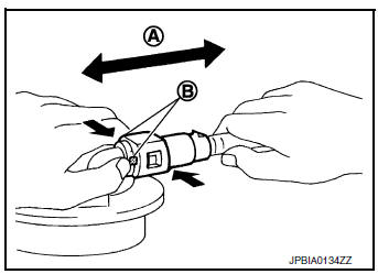
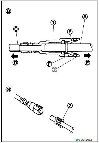
Disconnect quick connector as follows: Hold the sides of connector, press tabs and pull out fuel feed tube.
(A) : Pull If quick connector sticks to tube of main fuel level sensor unit, push and pull quick connectors several times until they start to move. Then disconnect them by pulling. CAUTION: Quick connector (1) can be disconnected when the tabs (F) are depressed completely. Do not twist it more than necessary.
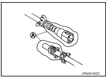
(B) : Connection (cross-section) Do not use any tools to disconnected quick connector. Keep resin tube (C) away from heat. Be especially careful when welding near the resin tube. Prevent acid liquid such as battery electrolyte, etc. from getting on resin tube. Do not bend or twist resin tube during installation and disconnection. Do not remove the remaining retainer (2) on hard tube (or the equivalent) (A) except when resin tube or retainer is replaced. When resin tube or hard tube (or the equivalent) is replaced, also replace retainer with new one. To keep the connecting portion clean and to avoid damage and foreign materials, cover them completely with plastic bags (A) or something similar.
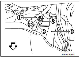
Remove center exhaust tube and muffler assembly. Refer to EX-5, "Exploded View". Remove protector from fuel tank. Remove vent hose (1) at rear side of fuel tank. Disconnect EVAP tube (2) at rear side of fuel tank. Instruction for quick connector (A) of EVAP tube. Refer to FL- 5, "Quick Connector". Remove fuel filler hose (3) at fuel filler tube side.
Remove parking brake cable bolts and separate parking brake cable from suspension arm. Refer to PB-7, "Exploded View". Remove rear suspension bars. Refer to RSU-22, "Exploded View". Support center of fuel tank (1) with suitable jack (A). CAUTION: Securely support the fuel tank with a piece of wood (B).
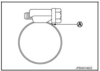
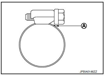
Remove fuel tank bands. Lower suitable jack carefully to remove fuel tank while holding it by hand. CAUTION: Fuel tank may be in an unstable condition because of the shape of fuel tank bottom. Be sure to secure fuel tank at all times. If replacing the fuel tank, remove the fuel level sensor unit, fuel filter and fuel pump assembly to transfer to the new fuel tank. Remove and discard the O-ring. Refer to FL-6, "Removal and Installation". INSTALLATION Installation is in the reverse order of removal. Fuel Filler Hose Insert fuel filler hose to the length below. : 35 mm (1.38 in) Be sure hose clamp is not placed on swelled area of fuel filler tube. Tighten the clamp hand with the top mark (A) until the mark is on the bolt head flange.
FWD : Inspection INSPECTION AFTER INSTALLATION Use the following procedure to check for fuel leaks. Turn the ignition switch ON (without starting the engine). Then check the connections for fuel leaks by applying fuel pressure to the fuel piping. Start engine, raise idle and verify there are no leaks at the fuel system connections. AWD AWD : Exploded View
Fuel filler cap Grommet Fuel filler tube Cover Clamp Fuel filler hose Clamp Vent hose Fuel tank protector Fuel tank strap (LH) Fuel tank strap (RH) Fuel tank To EVAP canister
AWD : Removal and Installation REMOVAL WARNING: Be sure to read “General Precautions” when working on the fuel system. Refer to FL-2, "General Precaution". Check the fuel level with the vehicle on a level surface. If the fuel gauge indicates more than the level as shown (1/2 full), drain the fuel from the fuel tank until the fuel gauge indicates a level at or below as shown (1/2 full). In case the fuel pump does not operate, use the following procedure. Insert fuel tubing of less than 25mm (0.98in) diameter into the fuel filler tube through the fuel filler opening to drain fuel from the fuel filler tube. Disconnect the fuel filler hose from the fuel filler tube. Insert fuel tubing into the fuel tank through the fuel filler hose to drain fuel from the fuel tank.
As a guide, the fuel level reaches or is less than the level on the fuel gauge as shown, when approximately 27.5
Release the fuel pressure from the fuel lines. Refer to EC-144, "Work Procedure". Disconnect negative battery terminal. Refer to PG-75, "Removal and Installation (Battery)". Unscrew the fuel filler cap to release the pressure inside the fuel tank. Remove second row seat (RH). Refer to SE-37, "Exploded View". Turn the four retainers 90 degrees to disengage the clips and remove the fuel pump inspection hole cover.. CAUTION: Cover the immeditate area surrounding the fuel pump inspection hole cover with plastic to avoid gasoline damage to carpet. Remove center exhaust tube and muffler assembly. Refer to EX-5, "Exploded View". Remove propeller shaft. Refer to DLN-99, "Removal and Installation". Remove protector from fuel tank. Remove vent hose (1) at rear side of fuel tank. Disconnect EVAP tube (2) at rear side of fuel tank. Instruction for quick connector (A) of EVAP tube. Refer to FL- 5, "Quick Connector". Remove fuel filler hose (3) at fuel filler tube side.
Remove parking brake cable bolts and separate parking brake cable from suspension arm. Refer to PB-7, "Exploded View". Remove rear suspension bars. Refer to RSU-22, "Exploded View". Support center of fuel tank (1) with suitable jack (A). CAUTION: Securely support the fuel tank with a piece of wood (B).
Remove fuel tank bands. Lower suitable jack carefully to remove fuel tank while holding it by hand. CAUTION: Fuel tank may be in an unstable condition, due to the shape of the fuel tank bottom. Be sure to secure tank at all times. If replacing the fuel tank, remove the fuel level sensor unit, fuel filter and fuel pump assembly to transfer to the new fuel tank. Remove and discard the O-ring. Refer to FL-6, "Removal and Installation". INSTALLATION Installation is in the reverse order of removal. Fuel Filler Hose Insert fuel filler hose to the length below. : 35 mm (1.38 in) Be sure hose clamp is not placed on swelled area of fuel filler tube. Tighten the clamp hand with the top mark (A) until the mark is on the bolt head flange.
AWD : Inspection INSPECTION AFTER INSTALLATION Use the following procedure to check for fuel leaks. Turn the ignition switch ON (without starting the engine). Then check the connections for fuel leaks by applying fuel pressure to the fuel piping. Start engine, raise idle and verify there are no leaks at the fuel system connections.
Other materials: Encoder circuit Periodic maintenance Symptom diagnosis © 2014-2025 Copyright
|